Seismic Detailing - Design Rules
Seismic Design Rules can be applied to Column, Beam and VBrace members in the model. The rules invoke various design or code check requirements according to AISC seismic design provisions (AISC 341, AISC 358). The program uses the 2005, 2010, 2016 or 2022 versions of these codes, depending on the HR steel design code settings in the Model Settings.
The design provisions primarily apply only to Hot Rolled steel members. However, the Overstrength design options apply to all members (of that particular Member Type) to which that seismic design rule has been applied. The reason for this is so that members (collectors or such) which require design to the overstrength provisions per the requirements of ASCE-7 can be automatically designed to the higher force requirements of the Overstrength load combinations.
The default entry for a member's seismic design rule is None which means that no special seismic detailing provisions will apply to the code checking provisions for that member.
General Frames and Columns
Seismic Design Rules: Hot Rolled Frame - General Columns
The first portion of the Seismic Design Rules under the Hot Rolled Frame tab applies to the steel frame in general and Hot Rolled columns.

Click on image to enlarge it
Seismic Design Rules: Hot Rolled Frame - General / Column Ductility
|
Column Header |
Description |
|---|---|
|
Label |
The label is a user defined text string which is used as a unique identifier for each of the seismic design rules defined for the structure. The program comes pre-loaded with number of generic seismic design rules based on AISC 341 seismic detailing specification. Click on the
Click on image to enlarge it |
|
Frame Type |
Frame Type defines the frame type (e.g. SMF, SCBF) for the frame. The program is pre-loaded with several typical seismic-force-resisting-systems based on AISC 341 seismic detailing specification. The program uses this entry to determine which code sections of seismic detailing requirements should be applied to members with the current seismic design rule. |
|
Column Ductility |
Column Ductility defines the ductility requirements for the columns.
|
|
Note:
|
|
|
Column Overstrength |
In seismic design some members may be required to be designed to an elevated / overstrength load. In RISA, this is done by creating load combinations with the Omega overstrength factors applied to the earthquake loads. If the column members are required to be designed to these load combinations, then this check box will be checked. |
|
Note:
|
|
 ellipsis in the Label column to open the Seismic Design Rule Editor window. This window lets you further define the frame type, member ductility, and member overstrength requirements, etc. You can choose either to use this editor window or the spreadsheet, to edit a seismic design rule.
Beams
Seismic Design Rules - Hot Rolled Frame - Beams
This portion of the spreadsheet contains information pertinent mostly for the design of hot rolled beams that are part of moment frames. The only exception to this is the Beam Overstrength option which applies to any beam member which is assigned the seismic design rule.

Click on image to enlarge it
Seismic Design Rules: Hot Rolled Frame - Beam Ductility
|
Column Header |
Description |
|---|---|
|
Beam Ductility |
Beam Ductility defines the ductility requirements for the beams. The definitions of High Ductility, Moderate Ductility, Minimal Ductility are described under the Column Ductility section above. |
| Connection |
Connection designates which of the pre-qualified moment connections defined in AISC 358 or its supplement are being used for the beam to column moment connection. The options are:
Note: The moment connection setting is used (in combination with the Frame Ductility setting on the column tab), to check some of the miscellaneous beam-column moment connection requirements per AISC 358. For example: if the beam to column connection is specified by the user as an Reduced Beam Section (RBS) then the column depth must be limited to a maximum of W40.
|
|
Beam Overstrength |
In seismic design some members may be required to be designed to an elevated / overstrength load. In RISA, this is done by creating load combinations with the Omega overstrength factors applied to the earthquake loads. If the beam members are required to be designed to these load combinations, then this box would be checked. |
|
Note:
|
|
| Z Factor |
This factor is used to define the reduction in plastic hinge moment expected for Reduced Beam Sections. Enter in the ratio between the plastic section modulus for the reduced beam section and the unreduced beam. For RBS connections this value will vary greatly, but will always be less than 1.0. The program will not allow a value of less than 0.1 to be entered in by the user. If this value is left blank, then no reduction in moment is considered. This factor will be used to determine the probable design strength and the strong column / weak beam moment ratio for the connection. It does NOT currently reduce the stiffness of the beam used in the analysis. Note: AISC 358 has some restrictions on the length and depth of cut that is allowed for the RBS section. RISA does not make any attempt to enforce these restrictions.
|
| Hinge Location |
This entry defines the location of the assumed plastic hinge (in inches) from the face of the column. This is used to determine the design moment at the face of the column as well as the strong column / weak beam ratio.
|
Braces
Seismic Design Rules - Hot Rolled Frame - Braces
This portion of the spreadsheet contains information pertinent to the design of hot rolled braces. The only exception to this is the Brace Overstrength option which applies to any VBrace member which is assigned the seismic design rule.

Click on image to enlarge it
Seismic Design Rules: Hot Rolled Frame - Brace Ductility
|
Column Header |
Description |
|---|---|
|
Brace Ductility |
Brace Ductility defines the ductility requirements for the braces. The definitions of High Ductility, Moderate Ductility, Minimal Ductility are described under the Column Ductility section above. |
|
Brace Overstrength |
In seismic design some members may be required to be designed to an elevated / overstrength load. In RISA this is done by creating load combinations with the (Ω0) overstrength factors applied to the earthquake loads. If the brace members are required to be designed to these load combinations, then this box would be checked. |
|
Note:
|
|
|
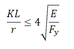
In seismic design some members may have the following restriction on the maximum slenderness (KL/r) value that they are allowed to have.
Examples would be AISC 341-05 braces that are part of a Special Concentrically Braced Frame (SCBF). This would also include AISC 341-05 and AISC 341-10/16/22 K, V, or inverted V braces in an Ordinary Concentrically Braced Frame (OCBF). |
|
Seismic Detailing Limitations
|
Limitation |
Description |
|---|---|
| Panel Zone Capacity | Currently, the program uses the elastic shear capacity equations (AISC 360-2022, eqns J10-9 and J10-10) for its code check of the panel zone. When plastic panel zone deformation is considered (along with shear capacity of the flanges) less conservative equations ( J10-11 and J10-12) may be more appropriate. |
| V and Inverted V Braced Frames & Gravity Loads | The requirement that the beam be analyzed as though the brace carried no dead or live load cannot be directly met in the RISA-3D analysis. However, this may be accomplished by integrating the model with RISAFloor, which automatically analyzes the beam for gravity loads as though the brace were not present. |
| Unbalanced Beam Force in Braced Frames | The effect of unbalanced brace forces is calculated only for beams in V or an inverted V frame configuration. This force is reported in the Seismic Detailing portion of the beam's detail report. However, this force is NOT used in the code checking of the beam UNLESS a capacity-limited (CL) load combination is used. For capacity-limited LCs (e.g. LC with ELX-CL), the program will apply brace expected strengths as seismic loads for columns and beams design. Under these load combinations, the beam unbalanced forces will be automatically considered in beam design by applying the capacity-limited forces. |
| Expected Strength of Braces | The effect of expected strength of braces is considered through the capacity-limited load combinations (e.g. ELX-CL, ELZ-CL) for columns and beams in braced frames such as SCBF and BRBF. Users need to select the supported design code (AISC 2010, 2016 or 2022), assign seismic design rules with appropriate frame type (e.g. SCBF or BRBF), and generate capacity-limited load combinations to perform capacity-limited design for columns and beams in braced frames. |